Foundation Loading Guidelines
By Jerry Senk, President of Equipment Manufacturers International, Inc.
ARTICLE TAKEAWAYS:
- Understanding static and dynamic load figures to pace positive or negative force into the foundation
- Dynamic load methods
FOUNDATION LOADING GUIDELINES
The following are considered good engineering practices and general guidelines for anyone considering foundation loadings for foundry equipment. This information should be included in any foundation plan delivered to a contractor or engineer.
The information is critical for proper design, especially considering the extreme duty presented by foundry molding and core making equipment.
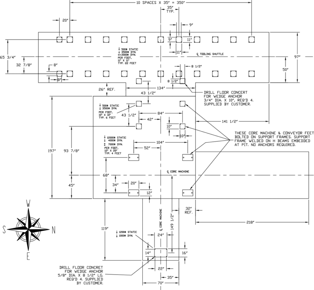
- STATIC & DYNAMIC LOADINGS
Any foundation pad must include static and dynamic loading figures. A coordinate system should be established to place a designation of positive or negative force into the foundation. It is generally accepted practice that a (+) sign denotes forces into the foundation, while a (-) sign denotes forces pulling at the foundation.
- LIVE & DEAD LOADINGS
Live and dead loadings do not have to be distinguished. Both are combined into the static loads noted above. For example, consider a mold line with flasks moving along it. The static load would include the conveyor itself plus the maximum load of the flasks.
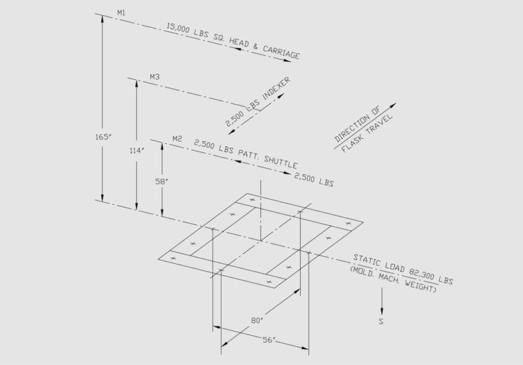
- OVERTURNING MOMENTS
The dynamic load should only include the overturning moment on the foundation pad. For example, if the same conveyor has a flask dead stop, this dead stop will create an overturning moment equal to the force of the flask multiplied by the perpendicular distance to the pad.
- DYNAMIC LOAD DESIGNATIONS
The dynamic load for each pad should be shown in any of the methods below:

- DRAWING METHODS
When drawing a diagram such as the one below, it is important to pick a point somewhere on the diagram, label it, and list the moments about that point.
- SAFETY FACTORS
Adding safety factors is good engineering practice. The suggested minimum safety factor is 1.75x. The guideline suggestion is that any foundation plan includes a statement of the safety factor used throughout the drawing. This is commonly listed in a NOTES section.
- DEFLECTION ON LOAD BEARING SURFACES
It is desirable to define a maximum deflection of the load-bearing surface. For example, a maximum deflection of 1/16” on both vertical and horizontal surfaces should be obtainable by most qualified foundation contractors.
- SHIMMING & LEVELING
High strength grout and Fabreeka pads are preferred to shims because they provide much better load-bearing capabilities than shims.
- CONTRACTOR MANAGEMENT
It is highly suggested that either the machine OEM or the responsible owner maintain open lines of communication with the foundation contractor. There is a varying degree of information required between foundation contractors, and being clear between owner and contractor will help to eliminate errors in design and execution.


